Disclaimer
Consultation before purchasing the intellectual product is necessary. A License and Stipulation Agreement will be created between the customer and the current Intellectual Property Owner. After that, you buy the Intellectual Property Product and download it. Your downloaded licensed intellectual property is password-protected; therefore, after purchasing the executable files in a double-layer zip file, you must contact us to receive the passwords to open the files.
Safety rules, usage, research, and development on the property must be strictly followed. Electricity is dangerous. Even high-voltage electricity at less than 1.6mA is dangerous. The research efforts show that the power source’s functionality is based on new physics. It’s not only about electricity and electromagnetic polarity anymore.
Patent Pending
All ideas, evolving or altered concepts, and illustrations published on this website describing the product in the “Shop” are patent-pending.
Alternatively, the way some developed technology here works is not by physical design; it’s about energy, allowing field harnessing. Therefore, design concepts may change after the website is upgraded or recovered from data loss.
Two rings of the Array
Each ring set consists of a large and small ring and is powered by two (2) output nodes; the larger ring is attached to node1 and the smaller ring to node2. The nodes inject non-reactive power between the rings and the cavity (R_RING). The cavity is called R_RING. R_RING is defined as a highly resistive cavity proportional to the medium (air or vacuum). We could imagine the cavity is either highly resistive or capacitive. There is a high-amplitude, non-reactive power solution for either circumstance. Therefore, a working design for one circumstance will satisfy both eventualities.
Potential Flight Systems
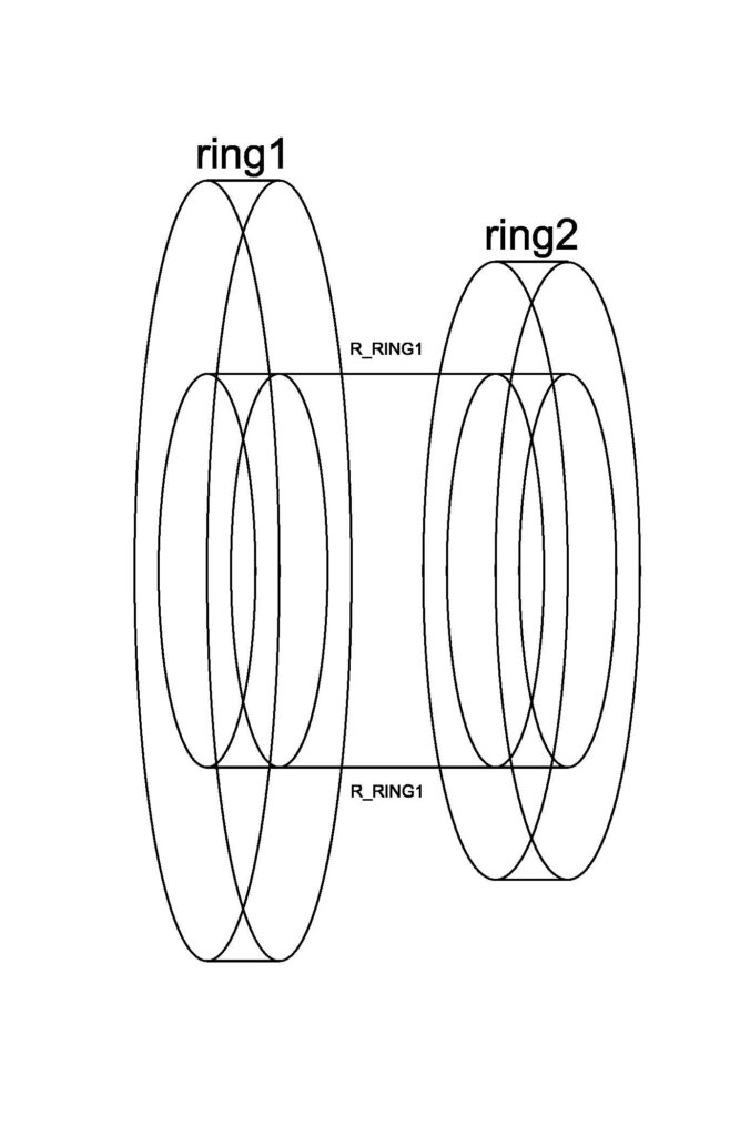
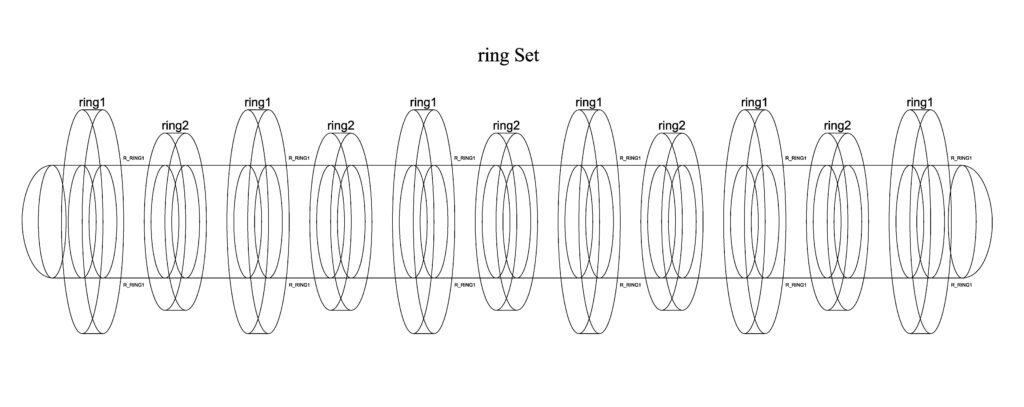
The ring set is an independent craft.
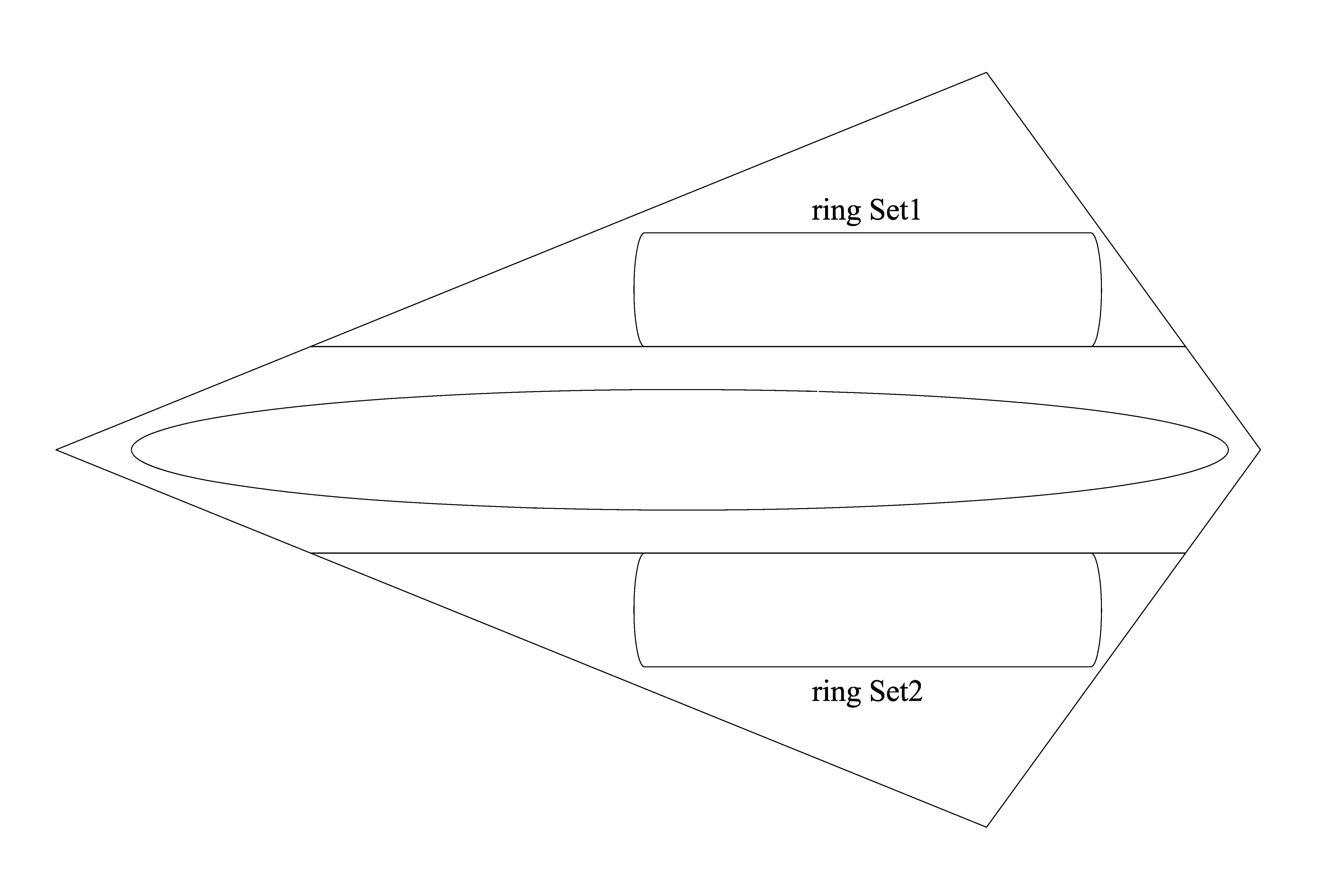
The “ring Set” is attached to the craft’s wings. The illustration was supposed to show the ring Set design to demonstrate one type of flyable craft; however, an evolvable concept made it more versatile when it could also fit on something that looks like a plane.
Node Power
Three power sources are used to demonstrate the effectiveness of multiple arrays.
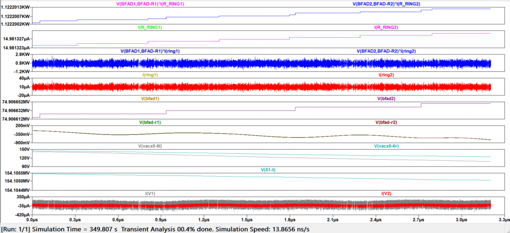
A Single Power Source Powering Two Rings
The ring array powers ON in a shorter time than a fourteen-ring array. It’s also less powerful than ring arrays with more rings.
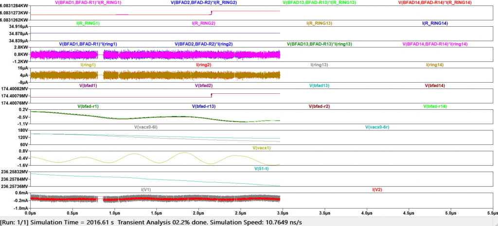
A Single Power Source Powering Seven Rings
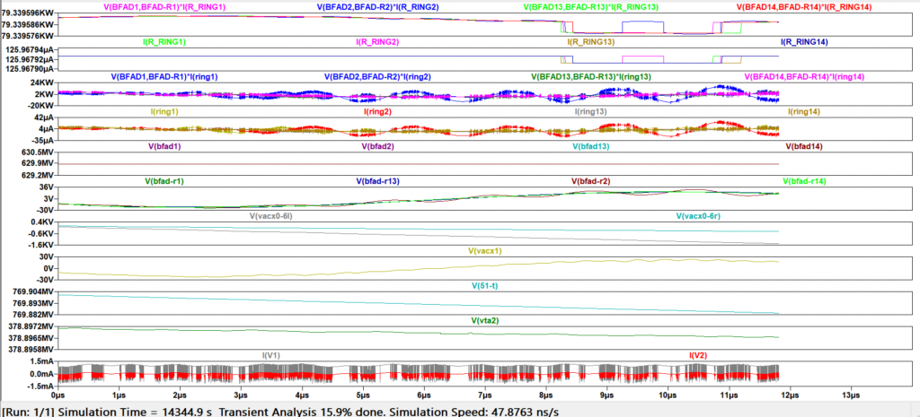
A Single Power Source Powering Fourteen Rings
Fields: Conductive Versus Cavity
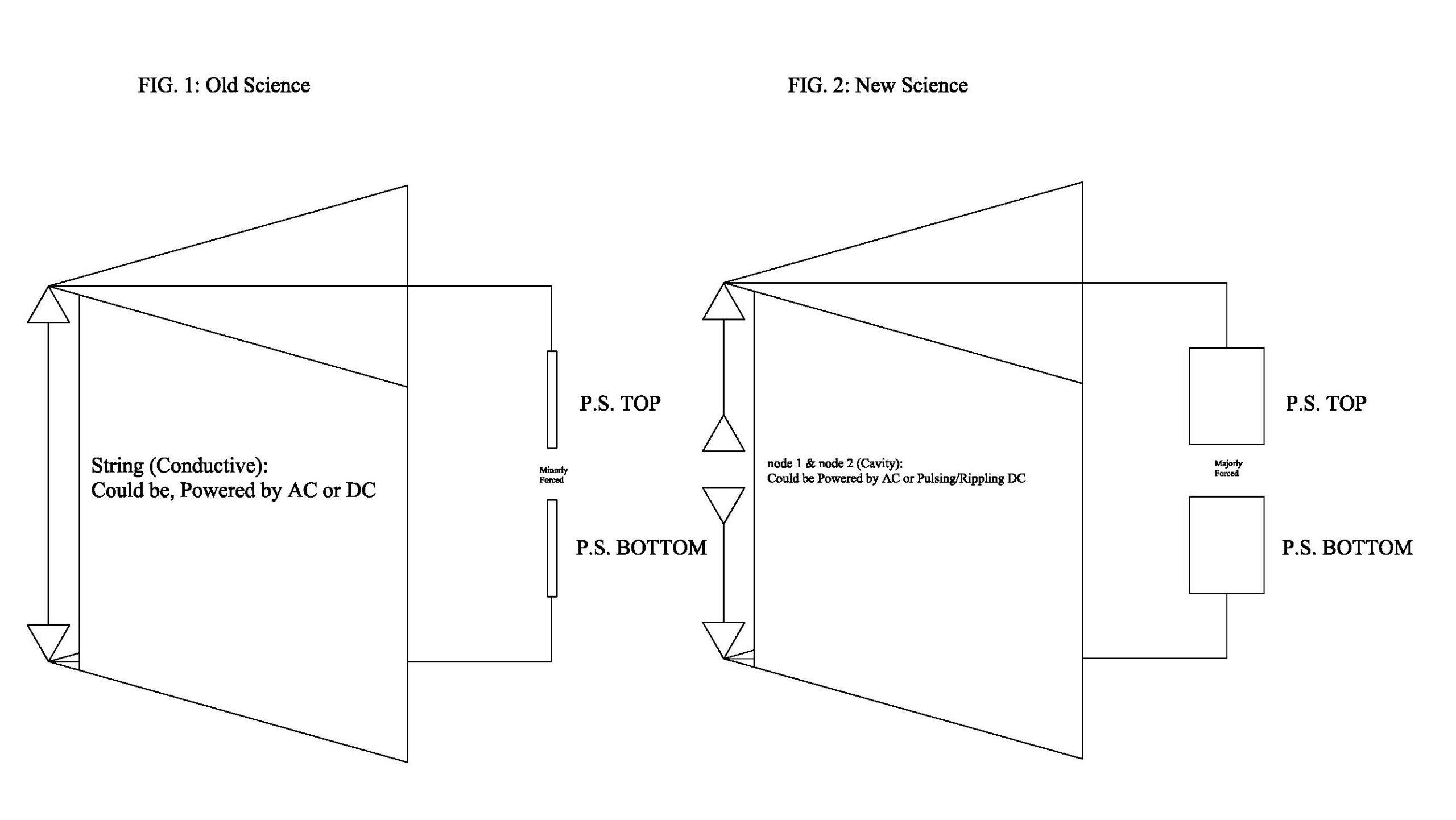
The scope of this product is about an opportunity to license and develop cavity-type field systems powered by an advanced power generation system. Compared with conductive-type field harnessing systems, cavity-type field harnessing systems require Force Component (Patent-Pending Claim) Power Sources (FIG. 2, powering potential) to operate efficiently. However, unlike conductive-type field systems, they aren’t limited by the ineffectiveness that concerns electromagnetism, which only works on ferromagnetic materials, charged materials, and so on. In retrospect, the R_Ring concept is viable only when the power source (P.S.) is enhanced by force components that enhance power output. Without harnessing power from that force, no electric propulsion system will match or surpass chemical rocket power.
Research Findings
A power source was designed with the potential to perform so well that it is self-oscillating and holds high-amplitude charges between isolated nodes. The threshold charges gained from the self-oscillating circuit keep the power source ON indefinitely.
Except for the “…Single Power Source Powering Two Rings”, all images show working modules or rings with the rest as background devices. It was necessary to do that to preserve the viewability of the output variables.
Researched and developed, the Power Source and Ring Array will enable the human race to achieve flight technology, with a renewable energy source to travel from Earth and through space.
Ring Array
Each ring, or multiple rings, could be driven by a single power source. Two output node groups (node1 and node2) are powered by injecting non-reactive node power into the cavity between cone-like rings.
Definitions
ring (Node to ring connections)
Node groups 1 and 2 are a general connection parameter for a ring set.
R_RING
R_RING represents the medium path between node 1 and node 2 (e.g., air, or the effective resistivity of solar wind particle density in space). This path is an actual gap in the physical spacecraft; the resistive element in simulation is a stand-in for the medium response across that gap.
Propulsion Ring Spacing
A “ring” refers to the 1 ↔ 2 node connection, or ring connection, for each ring module (the rings between the cavity or R_RINGs are 45° or other surface-degree ring sets). That’s between R_RING Spacings.
The SOA for this sort of technology lies in the realm shown by FIG. 1. FIG. 2 illustrates the product available for licensing on this website. It is an advanced physics concept.
R_RING Medium (Air, Resistivity 10e16 Ω)
Air resistivity, like vacuum resistivity, is high. Air resistivity is ~10e20 Ω/m. Even at closer distances between nodes, the resistivity does not change much.
The most important feature is that R_RING values can be as low as 1 Mega Ω and the output nodes stay functional at ~1.5 kW. That’s not better than some of the other solutions. Because it is what it is, in this case, it is.
To accumulate high-amplitude power between two or more nodes and interact with air without short-circuiting, using high current amplitudes and harnessing an electromagnetic field requires advanced circuit design.
The image below shows what happens when air resistivity interacts without using high current amplitudes. The air acquires oscillating resistivity properties:
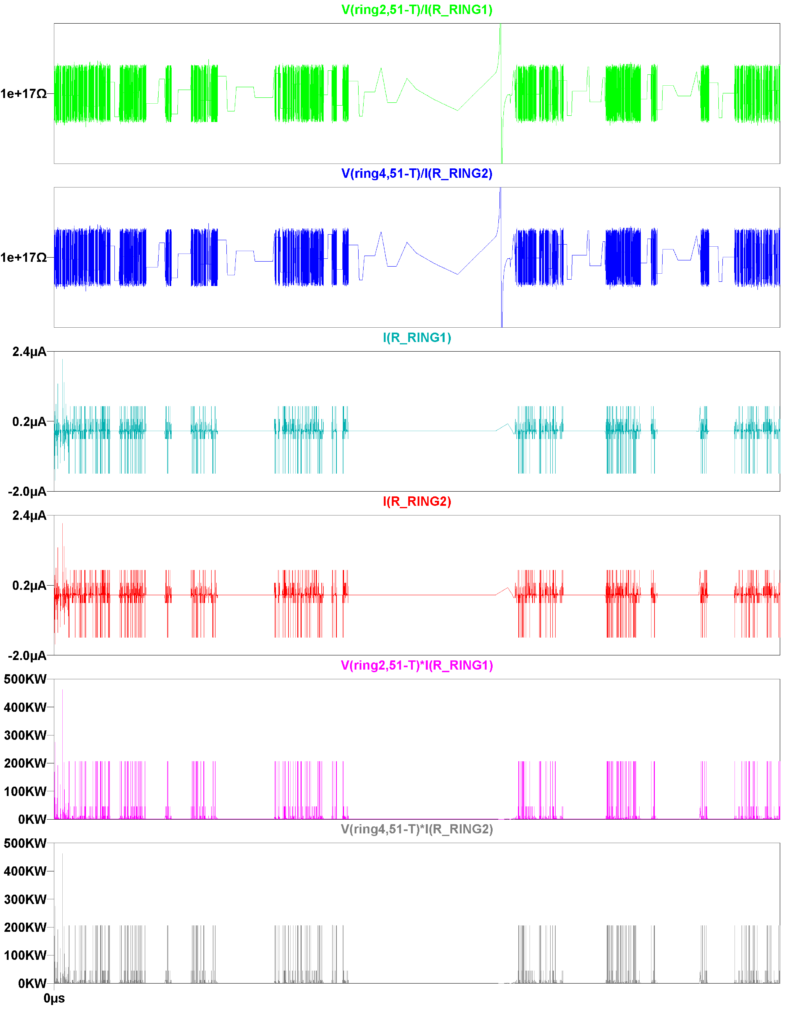
V51-T Voltage Substitutes for ring1 and ring3
In the simulation, rings 1 to 4 are conductors carrying current from the power source. They are output nodes used to harness the force needed to interact with air resistivity. In this developmental effort, high voltage isn’t the solution. Without the interactive power, no solution exists. Between the 4 nodes, R_RING medium resides. There are 5 R_RING medium areas of the power source. All except R_RINGs 1 and 2 are used to prevent damage to the circuit. All are used as propulsion-supporting junctions. However, they aren’t as important as R_RINGs 1 and 2. R_RINGs 1 and 2 are the main junctions used to harness propulsion Force.
The following image shows the output of 4 nodes and 2 ring sets. The ring sets have R_RINGs 1 and 2 in between:
The outputs achieved by the rings interacting with air are efficient. Straightforward: it’s F = ma, 1N = 1g/m and the power shown between R_RINGs 1 and 2 already represents the Force in newtons.
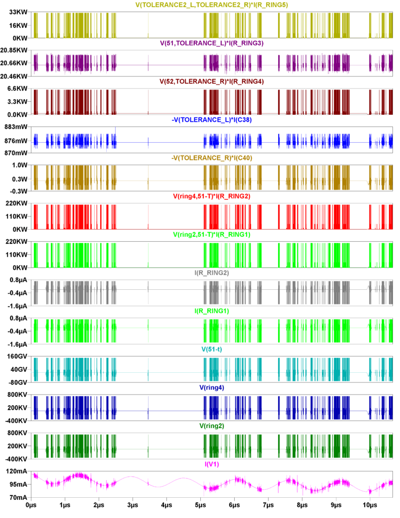
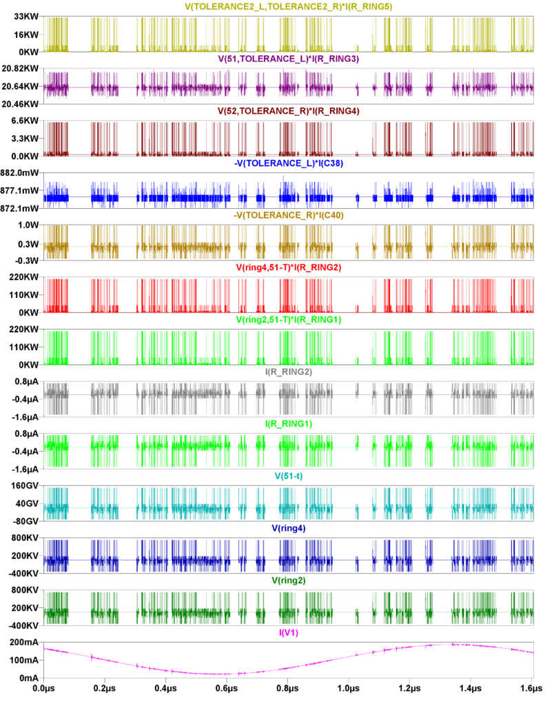
The following image shows the output of 16 nodes and 8 ring sets. The ring sets have R_RINGs 1 and 2 in between. Only two ring sets are shown in the image. The other ring sets are powered in the background of the simulation. Propulsion Forces harnessable by all 16 rings for a small-mass craft of 1000 kg allow an ~Average G Force of 1.6155079429e+02 g. It’s ~161.551 g. To allow an ~Average G Force of 4.0387698573e+00 g, two ring sets used by a ~10,000 kg craft must be used:
Safety
The power source maintaining power is straightforward:
Coupled with low-amplitude passthrough currents, low power output between the output nodes occurs when the initial resistive value is less than 1 Mega Ω. It doesn’t allow high-amplitude power retention. That means, when the power source is created and turned ON, the structural connections and functionality of the circuit will interact safely; coupled with low-amplitude passthrough currents, the highly resistive and conductive components connected between the PCB or circuit board, mixed with highly active pulsed power between nodes of the power source, won’t be problematic. Only highly resistive components retain power from the functioning circuit, and between those nodes are propulsion ring sets. If other nodes of the power source retain power and the output nodes are open with no component between, the open nodes are independent of the other nodes. Those nodes allow the power source to retain high-amplitude charges and could make or break that functionality through the interaction with resistive or capacitive elements between them. Resistivity below 1 Mega Ω will dissipate power from the power source, whereas higher resistive values will retain power.
Outputs of simulated R_RING medium components show a danger factor:
There is still a question about the voltage charges allowing high-amplitude power between the output nodes of the power source. Those safety concerns were categorized as potential stress nodes caused by high-voltage charges and the retention of high-amplitude, non-reactive continuous pulsed power. That power must be used between ring sets in propulsion schemes. There is also reactive power between some capacitors that was made tolerable.
Some capacitors that are now controlled or replaced in the circuit’s makeup were gaining high-amplitude reactive and non-reactive power between them. The non-reactive power was pulsed like the R_RING power outputs, and the reactive power outputs were doubly high (sinusoidal). Those danger factors for all capacitors were removed from the power source. However, although fashioned between known nodes attached to ring sets, dangerous propulsion energy still exists. With the diagnosis and repair of the power source, there should be no more unused nodes of the circuit. Some were attached to ring sets; capacitive components were replaced with resistive components so the junction could sustain low-amplitude power tolerance and retain low power amplitudes between the nodes. So far, all danger factors for the power source have been removed or diverted as propulsion nodes.
Hypothesis on Residual Potentials
Living Organisms:
Highly resistive or capacitive biological structures connected to conductive or low-resistance tissue do not retain high-amplitude power that would produce adverse biological effects. Because all known biological structures are connected to conductive tissue, high-amplitude power retention does not occur within living organisms.
No known living organism contains highly resistive biological structures that are completely isolated from conductive tissue; they have:
| Conductive fluids |
| + |
| Cell membranes (capacitive) |
| + |
| Resistive tissues |
Nonliving Organisms:
Highly resistive or capacitive elements connected to conductive or low-resistance materials do not retain high-amplitude power. Retention of high-amplitude power is only expected when highly resistive matter remains electrically isolated from conductive pathways. Compared with an actively charged circuit, high-amplitude power exists only at directly connected nodes, such as nodes connected to ring sets.
Highly resistive or capacitive elements connected to conductive or low-resistance materials do not retain high-amplitude power. Retention of high-amplitude power is only expected when highly resistive matter remains electrically isolated from conductive pathways. Compared with an actively charged circuit, high-amplitude power exists only at directly connected nodes, such as nodes connected to ring sets.
Hypothesis on Propulsion and Fields
Hypothetically, the voltage charges allowed by passthrough currents (AC: -1.6 µA to 800 nA) of the R_RING component or medium, at its standard resistive threshold in the research, aren’t dangerous. By the end of the research efforts and developments, in hands-on research, there will be evidence that voltage isn’t the problem or solution; power was reduced as the problem, and pulsed and non-reactive power are solutions for different things. It will prove that in this case, high-amplitude threshold voltages are byproducts of gaining those power sets. High–amplitude pulsed power is propulsion power, and Non-reactive High-amplitude Rippling Power is field energy.